Brief description
Principle
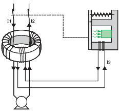
The main characteristics of RCD are shown in the below picture.
Its iron core surrounds all current-carrying conductors of an electrical circuit, and the magnetic flux generated in the magnetic core is related to the arithmetic and current of these conductor currents in an instant; the current flowing in one direction is assumed to be positive (I1), Then the current flowing in the opposite direction is negative (I2).
In a normal circuit without faults, I1 + I2 = 0, there is no magnetic flux in the magnetic core, and the electromotive force in the coil is zero. The ground fault current Id flows through the magnetic core to the fault point, but returns to the power source through the earth or through the protection line of the TN system.
The currents passing through the conductors of the magnetic core are therefore no longer balanced, and the current difference generates magnetic flux in the magnetic core.
This current is called "residual" current, and this principle is also regarded as the "residual current" principle.
The variable magnetic flux generated in the magnetic core induces an electromotive force in the winding, so that a current I3 flows through the coil that causes the trip unit to operate. If the residual current is greater than the current value that enables the tripper to operate, whether it is directly or electronically, the relay operates, the circuit breaker will trip.
The leakage current to the ground is like a transient overvoltage, and it does not appear because of a fault. They can cause RCD to malfunction. Some technologies have been developed to solve this type of misoperation.
Stable ground leakage current
Every low-voltage electrical device has its stable ground current, which is generated for the following reasons:
* The inherent capacitance imbalance of the live conductor in the three-phase circuit to the ground (1);
* Capacitance of single-phase loop live conductor to ground.
The larger the electrical device, the greater the capacitance and leakage current.
Filtering capacitors in electronic equipment (such as electronic equipment for automation, informatization, and computerization) often increase the leakage capacitance to ground significantly. When there is no more accurate data, the stable installation of 23OV and 50 HZ electrical ground The leakage current can be estimated with the following values:
* Single-phase or three-phase circuit: 1.5 mA / 100m;
* Floor heating: 1 mA / KW;
* Facsimile: 1 mA;
In a three-phase system, if the capacitance of the three phases to the ground is equal, the capacitance to the ground will leak
The leakage current will be zero, which is impossible in actual electrical installations.
* Information technology workstation: 2 mA;
* Information technology terminal equipment: 2 mA;
* Printer: 1 mA;
* Photocopier: 1.5 mA.
The RCD that meets the IEC and many national standards with a rated operating current of In can range from 0.5 I n to I n
Action within the range, so the leakage current of the loop after RCD must not be greater than 0.5 In.
In practical applications, the loop can be divided into smaller ones to limit the stable leakage current to 0.25In, which can avoid the malfunction of the RCD.
In very special circumstances, such as expansion or partial reconstruction of IT systems, the manufacturer must be consulted.
Transient leakage current
At the beginning of energizing the above capacitor, a very short high-frequency transient current can be generated, which is similar to that shown in diagram F68. When the IT system suddenly fails for the first time, due to the sudden increase in the relative voltage of the two non-faults, a high-frequency transient leakage current can also be generated.
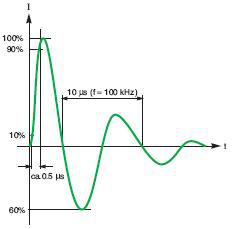
Standard waveform of 0.5us / 1OO kHz transient current.
Common mode overvoltage
The power network is subjected to overvoltages for various reasons: for example, atmospheric overvoltages, sudden changes in the operating conditions of the power grid (such as failures, fuse blows, switch switching, etc.), such sudden changes are often in the inductive and capacitive circuits of the system Cause large transient voltages and currents until a new stable operating condition occurs. The recorded data indicates that this overvoltage is usually below 6 kV in low-voltage systems, and can be approximately represented by a general 1.2 / 50us pulse waveform (see chart below).
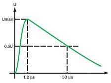
The standard waveform of 1.2 / 5us transient voltage.
This type of overvoltage can generate a transient current, which can be represented by a current pulse waveform of 8 / 2Ous, and its peak value can reach tens of A (see chart below).
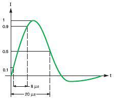
Standard wave form of 8 / 20us pulse current


 IPv6 network supported
 English
 français
 русский
 español
 português
 العربية
 हिंदी
हिंदी